
Introduction
As a boy, I remember seeing a dilapidated farm building that had a set of rafter ties in its attic. I noticed that the rafter ties had pulled away from the rafters they were nailed to. The rafter ties were clearly pulling away from their rafters because of the tension forces they were experiencing when under snow load. I noticed that steel cables has been hidden behind the rafter ties to try to reinforce them, but the screws attaching the cables to the rafters were also pulling out. This also was a sign of tremendous tension.
I had forgotten about this old farm building until I saw an article in the Journal of Light Construction (JLC) on the problems associated with using rafter ties on a roof. I became curious where the equation used in this article came from and I decided to derive it myself. I also noticed that the same equation is also built into an online calculator. Note that this post does not presume to train anyone on how to do structural engineering. Instead, I am reviewing the basic mathematics and physics used in doing this sort of work. See a structural engineer if you have a real problem that needs to be solved.
For those who are not familiar with rafter ties, I have included Figure 1 as an illustration of what they are and how they are connected to the rafters. The number of ties required per rafter will vary by situation. The rafter ties can generate tremendous force on the rafter to which it is connected. Purlins are often used in conjunction with rafter ties (see Appendix below for a figure).
 Collar Tie Illustration and Installation |
 Rafter Tie Illustration and Installation |
| Figure 1: Illustration and Implementation Examples of Rafter and Collar Ties | |
Analysis
Some Definitions
Mathematically, rafter and collar ties are handled the same way. However, each type of tie has a different purpose. Unfortunately, the terms collar and rafter tie are often conflated. I found a good set of definitions from a construction forum that I will use here.
- Tension Tie
- A structural member that is subject to net tension.
- Collar Tie
- A tension tie in the upper third of opposing gable rafters that is intended to resist rafter separation from the ridge because of wind or unbalanced roof loads. Collar tie is a colloquial term for collar beam.
- Rafter Tie
- A tension tie in the lower third of opposing gable rafters that is intended to resist the outward thrust of the rafter under load.
Figure 2 is an illustration of a roof constructed using rafter ties.
Figure 2: Illustration of Roof with Rafter Tie.
Calculating Roof Loading
Figure 3 shows how the loading on an individual rafter is defined. Observe that all the loads are specified as if they were projected onto the horizontal plane.

Figure 3: Illustration of a Rafter's Tributory Area.
The total load on a rafter is given by W, which is calculated using Equation 1.
| Eq. 1 | 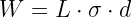 |
where L is the rafter length projected onto the horizontal plane, d is the rafter tributory width , and σ is the roof loading projected onto the horizontal plane. The use of projections onto the horizontal plane seems to be the most commonly used approach.
Rafter and Collar Tie Tension Equation
To establish the relationship discussed in the article, we need to observe that the sum of the angular momentums must be 0. Consider the following free body diagram (Figure 4).

Figure 4: Free Body Diagram of the Rafter.Moments are summed about a point on the ridge of the roof. For details on computing the moment due to the distributed load, see the Appendix at the bottom of this post.
For a static (i.e. non-rotating) situation, the moment about ridge beam connection exerted by the tension tie must equal the moment exerted by the support reaction and the distributed load (Equation 2).
| Eq. 2 |  |
This form is correct, but a more useful form for this discussion substitutes the roof slope and height for L.
| Eq. 3 |  |
Equation 3 is presented in the JLC article. This equation can be modified to produce Equation 4, another commonly seen result.
| Eq. 4 |  |
where w is the unit loading (lbf/ft) along the rafter, expressed as force projected horizontally per unit length.
Worked Example
I plugged the JLC example into Mathcad to verify that I get the result that JLC obtained (Figure 5). Note that this example assumed that the dead load had already been projected onto the horizontal plane.

Figure 5: JLC Example in Mathcad.
Conclusion
Using basic statics, I have derived the equations used in in determining the tension in rafter and collar ties. I have duplicated a worked example from JLC magazine. This exercise has shown me that rafter and collar ties are subject to enormous tension forces. These forces make securing the ties to the rafters an engineering challenge. The tension is so high that a large number of nails/screws would be needed for each joint. In fact, so many fasteners are needed that the joint may weaken because of having so many fasteners in a relatively small area.
I also learned that rafter and collar ties have different purposes: collar ties help secure the rafters to the ridge beam during periods of unbalanced loads (i.e. from wind or asymmetrical snow load); rafter ties are used to counteract the outward thrust of the roof.
Note that this post reviews the mathematics performed by a licensed structural engineer in a construction industry publication. It is not intended to be a tutorial on designing rafter or collar ties. That is a job for a professional.
References
- 18th Annual Eastern Conference of the Timber Framers Guild (Article: Pity the Poor Rafter Pair)
- Interesting forum discussion
- The mechanics of architecture -- free Google Ebook that actually works this problem on pg 121.
Appendix
Calculation Detail on Moment from a Distributed Load
There is a bit of calculus work associated with modeling the moment due to the distributed load along roof. Figure 6 illustrates this computation.

Figure 6: Illustration of Moment Calculation for a Distributed Load.
Illustration Showing Purlins and Collar Ties
The following figure is from this source.

Figure 7: Illustration of Collar Ties with Purlins.
Very interesting use of Mathcad to explore and explain a common concern amongst homeowners living in a snow belt. Thanks for sharing your mathematical curiosity and skill!
I love Mathcad. I have made it the standard for my engineering team. I can't wait to see what you folks do with Mathcad Prime.
Not sure about this equation.
In Figure 4: Free Body Diagram of the Rafter. the reaction at the plate should be W not W/2 because the roof is not supported at the ridge as in a ridge beam configurations.
All the weight is on the outside wall with triangulation type roofs.
My whole FBD is incorrect. I have corrected it and cross checked the answer with reference 3. Thank you for the close review.
Mathscinotes
Since L is the half-width of the roof, the load should be W, not W/2 and there are other serious things wrong with this. Firstly the tributory width d should be 3d as only every third rafter is tied; also the un-tied rafters push on the wall plates which span between the tied rafter ends bringing in 2/3 of the load on the tie and adding to the bending in the tied rafters. When not every rafter is tied it is usual to use a purlin supporting the un-tied rafters spanning between the tied rafters.
Hi Bill,
You are correct. I have updated my FBD. It looks like my final result stays the same (dumb luck). I VERY much appreciate your review.
mathscinotes
It's really nice to see more mechanics maths - it's been too long.
It doesn't affect the calculation, but you're missing the reaction at the ridge (T), without which you don't have horizontal equilibrium.
Thanks for the catch! I will update.
mathscinotes
I am a qualified Civil Engineer and it is a nice surprise when someone takes an interest in your own field. Carpenters have been doing all this by trial and error and feel since the Middle Ages. Many of the early rail bridges in USA were in timber with trusses and steel tension rods along similar lines. Structural theory came along much later to often prove none of it could stand up despite it mostly serving long after any theoretical design life. Medieval "architects" (stonemasons) were also masters at building with stone. But as cathedral design evolved, some medieval architects began to push beyond the boundaries of known structural design and into unknown territory.
http://www.pbs.org/wgbh/nova/physics/arch-physics.html
I am an electrical engineer by trade, but I must say that I stand in awe of the long history of civil engineering. I think civil engineering is a beautiful subject. I have been reading a couple books about civil engineering (Structures by J.E. Gordon and Structural Analysis by Kassimali). These books have motivated me to try some analysis and I have enjoyed it. As a rookie, I make mistakes. Fortunately, people have been very helpful.
I always need to emphasize to my readers that I am NOT a structural engineer, but merely a person trying to understand how the world works.
mathscinotes
I am another Electrical Engineer who took an interest in Civil and Mechanical Engineering. In fact, I considered switching majors and took courses in Strengths of Materials, Materials Science and Thermodynamics to prepare for the switch, but I couldn't quite bring myself to make the jump to the other fields. I'm now retired, and I like to continue to learn, so thanks for the short tutorial!
A couple of notes that might help clarify things;
Fig 1 illustrates rafter ties. The rafter ties are incorrectly labelled as collar ties. The upper collar tie does not experience the tension that the lower rafter tie is resisting, if that tension is resisted in the upper third the roof is probably on the ground. The prescriptive provisions of the building code require rafter ties on EACH rafter pair and collar ties every 4'. An engineer can design a roof with rafter ties on wider spacings, look at the ridge and/or wall plate as a beam if doing that.
The bolts shown are not typically the way a conventional residential roof would be framed. Wood is not particularly strong per unit of area and has a real tough time with tension perpendicular to grain. Many small fasteners distributing the load over a larger area is a better way to connect the tie in most situations. Think about the many small "nails" in a lightweight truss's gang nail plates. Bolts work but go carefully.
This is an image showing several methods of installing the upper collar ties, the lower rafter ties can be seen down near the feet of the rafters.
[img]http://i180.photobucket.com/albums/x109/windyhilll/collarties.jpg[/img]
In fig 3 the rafter spacing "d" is incorrectly labelled "rafter pitch". I understand the useage but in common parlance we are already using the term pitch to denote the rafter slope.
As the rafter tie is raised it puts a bending load on the rafter at the point of connection, the rafter needs to be deeper as the tie is raised.
This is a picture of another way of framing a roof, a heavy timber truss at very wide spacing. As you can imagine the tension is getting up there. Rather than trying to fasten the tie to the top chord I buried it into the tie, the connection is now in compression. Shear in the relish beyond the rafter foot and crushing of the wood in the birdsmouth are checks that must be performed there.
[IMG]http://i180.photobucket.com/albums/x109/windyhilll/heel.jpg[/IMG]
The link to my calc is broken in the article above, this is a good link;
http://www.timbertoolbox.com/Calcs/raisedtiethrust.htm
Thanks again for your work, good stuff!
Hi Don,
Your the best!
Here is what I have done:
1. I have augmented Figure 1 with illustrations and photos of both collar and rafter ties. My previous illustration was based on a construction magazine article that was mislabeled. I simply missed it.
2. I have corrected the link to your calculator.
3. I have changed the label on Figure 3 to state "rafter separation" to remove confusion with pitch.
4. I no longer show the bolted connection.
Again, thank you very much.
Hi, thanks for this elegant solution since I had been triangulating loads and resolving through angles... a much more convoluted route with more chance for errors. One thing I note from your analysis is that the thrust T is fine for calculating the load upon the tie to rafter connection, but since this analysis considers only half the roof, the same effect on the other half of the roof would therefore create a tensile force in the tie member of 2 x T. This distinction should be made to avoid confusion. Fortunately, however, it is the connection that is the weak link in this scenario and with timber, I have found the tie should be able to withstand more than twice the load that a bolted connection will withstand for the same cross section, so hopefully no disasters out there waiting to happen 🙂
I will immediately grasp your rss as I can't in finding your e-mail subscription hyperlink or e-newsletter service.
Do you've any? Kindly permit me recognise so that I may just subscribe.
Thanks.
I do not understand your question. Can you restate it?
Fig. 7 "Illustration of Collar Ties with Purlins" is confusing. Where are the purlins? Nothing on the diagram is labeled "Purlin". And why choose an uncommon spacing of 900 mm for rafters and battens? Makes more sense to use a spacing which is modular with plywood such as 400 or 600 mm.
Also, the presence of an interior wall and prop is inconsistent with the analysis above. They may be used in certain cases, but the statics would be completely different than those represented in the calculations in the analysis above.
What is the point of using ceiling battens under the ceiling joists (rafter ties) if they are spaced at 450 mm? It would be more usual to apply the ceiling directly to the underside of joists and space the joists at 16" (406.4 mm) centers.
4/12
24" rafter spacing.
No rafter ties at all. A few existing collar ties.
ceiling joists run parallel to ridge.
house is 27' x 30'(ridge).
7/8" roof planking and asphalt shingles.
Hi Paul,
I am not a structural engineer and I cannot comment on any specific circumstance. This blog post really is really just some personal notes on an article I read in JLC.
mathscinotes
oh, I thought there was math here to figure roof dead loads.
trying again...why does this site keep saying my pswd is wrong and then saying its saved, but its wrong again, then my post gets lost?
my post above 15 june 2014 1;10am also asked for help, That part of my post was here, now its gone. I cant get this formula to work for me. See my thread start here: http://www.diynot.com/forums/building/rafter-ties.409264/#3170605
ok, I checked the notify me checkbox, but right as I clicked to send my post, it unchecked, so I try again.
Pingback: Brand Identity: Renovate or Build from the Ground Up? | The Clyde Fitch Report
If the wall of the house is able to resist a horizontal force there will be a reaction there and consequently the structure can't be solved by statics. Before the ubiquitous use of computerised F.E analyses, this book: http://www.amazon.com/Rigid-Frame-Formulas-Adolf-Kleinlogel/dp/0804445516 was used to solve indeterminate structures and today with Mathcad it is still useful for parametric studies before starting a detailed computer model. If you can get hold of a copy, Frame 17 is the one that solves a collar roof structure for all conceivable loading conditions.
Incidentally, when will the U.S adopt the S.I. system of units? During my school days I was subjected to the full horror of the old imperial set of units, complete with gallons, acres, chains, fathoms, yds, ft, ins, tons, cwts, stones, pounds and ounces as well as pounds shilling and pence just to make any problem so opaque that the underlying physics just couldn't be appreciated.
First, thank you for the reference. I will check my used book sources.
As far as imperial units go, I cannot stand them. It is interesting that at work I only use metric – this has been true for decades. It is when I go home and deal with the construction industry that I must revert to imperial units. Another big gripe I have is letter-size paper. I would much rather have A4 paper as the standard. At least then we could conveniently scale copies up and down.
mathscinotes
Wow this is so interesting! We are just about to get a wooden roof put on our brick built house after 10 years living under corrugated sheets (in southern Spain!) - have professionals doing the building but was looking around for ideas and to inform/educate myself. (House approx 15m x 6m, single storey). - I was searching for ideas of how to finish off the "ceiling" with laminated flooring etc! So .... got a fairly good grade for maths at 16 (1979), geometry was interesting, Pythagoras, areas of circles etc ... loads that meant nothing to me though. The above is a bit above my pay-grade ... how much more interesting and relevant maths would have been if they'd related it to something REAL like this - thank you!
Hi mathacinotes!
Stumbled across your site today. Trying to get some info on when/if I am required by code to install rafter ties. I am building a small 16x32 cabin with cathedral ceiling. Rafters are 2x8 with a 2x10 ridge board. Roof pitch is 9/12 and again, the building is only 16 ft wide. I also have a center support wall in the middle of the 32ft (at 16ft). So, with a 16ft wide cabin and a 9/12 pitch with 2x8 rafters 24 in o.c.- can I get away with no rafter or collar ties and just leave the cathedral completely open?
Thanks for any info you can provide me!
Garrett
g.roush@outlook.com
I am not a structural engineer – just an electrical engineer who thinks structures are interesting. I cannot offer you advice.
mathscinotes
Garrett,
Here in the UK there is a code of practice for roof trusses which specifies loads and load combinations to be used for structural analyses. For a combination of self-weight plus snow load on a single truss using your c/c distance of 2ft and a roof slope of about 36 degrees the total applied force works out at 48 lbf/sq. ft. Of course, this figure is specific to local conditions here and may not be applicable to your location. There are formulae in text books which will give forces at the supports and for a 16ft span I’ve used one such formula to calculate equal and opposite horizontal forces at the supports of 324 lbf, in addition to vertical reactions of 384 lbf. If you had horizontal ties they would each have to resist a tensile force of 324 lbf which is not too difficult but in their absence your supporting structure would have to be capable of transferring a total horizontal thrust of 15 x 324 = 2.2 tons to the foundations, which is a bit more problematic. Of course, the old medieval cathedral builders would use flying buttresses to achieve this, but I assume your description of your building shouldn’t be taken too literally!
Instead of opting for tie members at the eaves level, you could give yourself more headroom by fixing the ties to the rafters at some point intermediate between the eaves and the ridge. Depending on the level of the ties it may be possible to reduce the thrust at eaves level to something manageable, but you would still have to find a way to manage it.
I hope this has been of some assistance
Best regards,
Malcolm Frame
Hello, This is very helpful analysis for thrust calculation. Could you help me understand the variable p = 2ft for Rafter Pitch in Figure 5. Thank you
Pingback: Moving collar ties?
I think that is pretty interesting that you would multiply d by sigma and length. I have been wanting to learn a little more about construction because I think it would be cool to be able to do some roof repairs in the future. I'll have to make sure that I pay attention to the math so that I don't mess up on one of the trusses.
I am building a 12x12 screen house .
The building code office said I need to have a roof that will handle 95 lbs per square foot.
6/12 pitch. What framing do I need? can you help?
Sorry, Robert. I am not a structural engineer and cannot provide you with building advice. My goal with these blog posts is to illustrate how simple mathematics is used to solve real-world problems. The application of this knowledge to specific problems involves training and experience beyond what I have.
mark
Pingback: Wood Plane Length And Width Measurements – woodoo