
Quote of the Day
Journalism is printing what someone else does not want printed; everything else is public relations.
Introduction

Figure 1: Typical LMT70 Application Circuit. My application circuit will be VERY similar. (Source)
I have decided that my next home electronics project will be a precision thermometer that I can read over the Internet. I will be mounting the sensor at my cabin in Northern Minnesota, where winter temperatures can drop to -40 °C or lower. During the summer, temperatures can rise to nearly 40 °C. My plan is to connect the unit to a Raspberry Pie that I use to provide remote monitoring and control. I decided that I going to use a Texas Instruments' LMT70 precision temperature sensor, which uses a well-known circuit called a Brokaw bandgap reference to measure the temperature of its die.
This post documents how I familiarized myself with this part and how it works. My Mathcad and LTSpice source files are included here.
Background
Definitions
- Breakout Board
- Breakout boards are small PCBs on which you can mount an integrated circuit and that provides you readily accessible points for connecting the integrated circuit pads/balls to the outside world using pins and wires. This web page shows a good example of breakboard application.
- Bandgap Reference
- A bandgap voltage reference is a temperature-independent voltage reference circuit widely used in integrated circuits. It produces a fixed (constant) voltage regardless of power supply variations, temperature changes and circuit loading from a device. Normally, bandgap reference circuits cancel out two opposing variations caused by temperature. For temperature measurement, we will not be cancelling out the temperature variation – we will use the very predictable variation present in part of the circuit to measure the die temperature of the LMT70. In general, the die temperature is strongly correlated with the ambient temperature. The relationship between ambient temperature and die temperature is usually established empirically.
- Proportional to Absolute Temperature
- A circuit parameter (e.g. voltage) that is proportional to the LMT70's absolute die temperature, ie. temperature measured in Kelvin. Note that transistors do not work at absolute zero, but the linear response will extrapolate down to 0 K.
Requirements
This is a home project, which means my requirements will be fairly simple:
- The sensor must be able to measure a range of temperature from -40 °C to 40 °C.
The LMT70 is capable of measuring from -55 °C to 150 °C, so it has plenty of dynamic range.
- I am looking for an accuracy of ±0.5 °C.
The LMT70 is rated for ±0.36 °C over the range of -55 °C to 150 °C. I need to ensure that the error introduced by my A/D conversion does not cause my overall error to exceed my requirement.
- I need to be able to mount the sensor onto a board that I can build.
- Here is a good discussion on reddit about prototyping with the DSBGA package.
- You can buy the LMT70 already mounted on a breakout board on ebay.
- The sensor must be capable of being shutdown and only activated periodically.
This is my approach for minimizing the error due to self heating. I plan on having the sensor off most of the time and only turning it on for a few seconds every five minutes or so. This approach will minimize the error from self-heating.
Brokaw Cell
The LMT70 uses a Brokaw bandgap reference circuit that can produce an output voltage that is proportional to the absolute temperature. The circuit is well-described on the Wikipedia, so I refer you there for more details. I do want to point out an excellent video presented by A. Paul Brokaw, the developer of the circuit. You rarely see a circuit design presented by its original developer, so this video is a treat.
Voltage Proportional to Absolute Temperature
Equation 1 is describes how the output voltage from a Brokaw bandgap reference varies with absolute temperature. I derive Equation 1 in Figure 2. R1 and R2 are resistors shown in Figure 2.
| Eq. 1 | 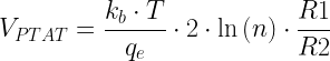 |
where
- kb is Boltzmann's constant.
- qe is the charge on an electron.
- T is absolute temperature.
- n is the number of parallel transistors in series with R2.
- VPTAT is a voltage that is proportional to the absolute temperature T.
Except for temperature T, all parameters on the right-hand side of Equation 1 are constants. Thus, Equation 1 describes a linear relationship between VPTAT and T.
Analysis
Output Voltage Derivation
Figure 2 shows my Brokaw reference circuit built using 2N2222 transistors and a generic high-gain opamp. You can see my Spice commands on the left for setting up the simulation – perform a 1 msec transient analysis at temperatures from 10 °C to 70 °C in steps of 10 °C. I also include my derivation of Equation 1 as it applied to the circuit in Figure 2. In this Brokaw realization, the voltage sum of the VBE across three (n = 3) transistors (Q1, Q2, Q3) plus the voltage drop across R2 is forced to be equal to the VBE drop across Q2. The derivation is easily extended for any number transistors (n > 1).
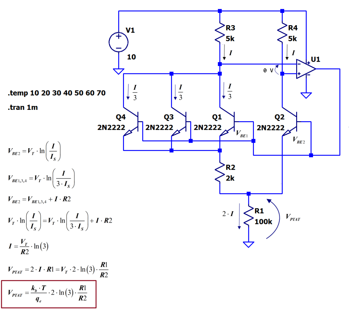
Figure 2: LTSpice Example Circuit and My Derivation of Equation 1.
LTSpice Simulation
Figure 3 shows the results of my LTSpice simulation. I ran the simulation over a temperature range from 10 °C to 70 °C in increments of 10 °C. In Figure 3, the red line corresponds to 10 °C and 70 °C corresponds to 70 °C. I could have ran the simulation over a wider range, but my interest here is expository – the parts have a guaranteed level of accuracy over a temperature range from -55 °C to 150 °C.

Figure 3: LTSpice Simulation of Brokaw Cell.
Simulation Results Versus Theoretical Prediction
Figure 4 plots Equation 1 and my LTSpice simulation versus temperature. As you can see, the agreement is excellent.

Figure 4: LTSpice Graph of Brokaw Bandgap Reference VPTAT for Various Temperatures.
Conclusion
I go through an analysis like this every time I use a part for the first time. I use a combination of Mathcad and LTSpice to develop simple models for predicting circuit behavior and optimizing my designs.
Hello,
Enjoying your blog very much - thanks for sharing.
I've got my RPi working with an ADT7420 (I2C interface) and a ADT7320 (SPI) temp sensor.
They are LFCSP packages so only a bit easier to hand solder. The package has a large central pad on the bottom, so perhaps better thermal sinking to the board.
Seems like they have a similar range and accuracy as well. I haven't read what temp transducer is inside though, so would be hard to model (haven't checked if they have a Spice model available).
Just wondered if you had considered these for your application.
I had not looked at the ADT7420 or ADT7320 and should have. I grabbed a part that coworkers had used for interfacing to a 4-20 mA current loop. I like the "all-in-one" approach used by the Analog Device part. Thanks for the reference.
mark