
Quote of the Day
A leader is a dealer in hope.
— Napoleon Bonaparte

Figure 1: My Garage at Night.
As I have mentioned in other posts, I am building a large garage in northern Minnesota (Figure 1). I would show you some pictures of the interior, but I have promised my son that I will not post anything that could ruin his surprise when he sees it in April. As part of this construction effort, I am using quite a bit of electrical conduit. Conduit consists of metal pipes (often called EMT) through which the wires pass and it must be bent to go around any barriers it encounters. Conduit is a very efficient way to wire a working area because it directly attaches to the wall and does not require opening holes in drywall and repairing the damage. Conduit can also be updated and modified easily by running new/additional wires through it.

Figure 2: 4-Point Saddle Bend Around An
Obstacle. (Source)
I am going to review the process for running conduit around an obstacle using a 4-point saddle bend, which entails bending the conduit into a trapezoidal shape for passing around the obstacle (Figure 1). Electrical handbooks contain tables that tell electricians how to measure along the conduit so that the bend will go around an object of a given depth. These tables generally ignore the bend radius of the conduit bender. In this post, I will provide simple formulas used to create the standard tables and will use these formulas to regenerate a commonly seen table for conduit bending. I will also derive the more complex formulas that use the conduit bender radius to achieve a more exact result.
For those who like to follow along, my worksheet is here.
Background
Reference Article
In this post, I will duplicate a conduit bending table that I saw in this excellent reference article. The table is shown in Figure 3, which has units of degrees for angles and inches for length.

Figure 3: Bend Table That I will Duplicate in Excel.
Conduit Bending Video
Figure 4 shows a conduit bending video by a local trade school (Dunwoody) that I think is first-rate. The instructor covers both 4-point (trapezoid) and 3-point (triangular) bends. My focus in this post is the 4-point saddle bend because that is what I am dealing with in my garage construction right now.
| Figure 4: Good Briefing on 3-Point and 4-Point Saddle Bends. |
Conduit Bending Formulas
Conduit Bending Formulas Ignoring Bend Radius
There are two formulas that I need to generate: (1) shrinkage, which is the reduction in horizontal length caused by the bend; (2) bend distance, which is the horizontal length of the bend region. Figure 5 illustrates the geometry of the situation.

Figure 5: Key Conduit Bending Formulas Ignoring Bend Radius.
Applying basic trigonometry to Figure 5, we can derive Equations 1 and 2.
| Eq. 1 |  |
| Eq. 2 |  |
where
-
- BD, Bend Distance is the horizontal distance between bends.
- BO, Bend Offset is the depth of the obstacle to be passed over.
- Θ is the angle of the bend.
- S, Shrinkage is the effective reduction in horizontal conduit length because of the bend. Essentially, it is the difference in length between the hypotenuse and the base of a triangle.
I will use these equations to generate the table shown in Figure 3.
Conduit Bending Formulas Compensating for Bend Radius
Again, there are two formulas that I need to generate: shrinkage (Equation 3) and bend distance (Equation 5). An additional formula for the straight pipe length is also provided (Equation 4). Figure 6 illustrates the geometry of the situation and the associated formulas. The radius of the conduit bender, called R, will vary for each conduit bender. It normally is stamped on the bender, or the information is available in the vendor's literature.

Figure 6: Key Conduit Bending Formulas (Compensating for Bend Radius).
Applying basic trigonometry to Figure 5, we can derive Equations 3, 4, and 5. Note that BD is defined slightly differently in that it represents the center-to-center distance between the bends.
| Eq. 3 |  |
| Eq. 4 | ![\displaystyle SL=\left[ {BO-2\cdot R\cdot \left( {1-cos\left( \theta \right)} \right)} \right]\cdot \csc \left( \theta \right)](https://s0.wp.com/latex.php?latex=%5Cdisplaystyle+SL%3D%5Cleft%5B+%7BBO-2%5Ccdot+R%5Ccdot+%5Cleft%28+%7B1-cos%5Cleft%28+%5Ctheta+%5Cright%29%7D+%5Cright%29%7D+%5Cright%5D%5Ccdot+%5Ccsc+%5Cleft%28+%5Ctheta+%5Cright%29&bg=ffffff&fg=000&s=1&c=20201002) |
| Eq. 5 | ![\displaystyle BD=R\cdot \theta +\left[ {BO-2\cdot R\cdot \left( {1-cos\left( \theta \right)} \right)} \right]\cdot \csc \left( \theta \right)](https://s0.wp.com/latex.php?latex=%5Cdisplaystyle+BD%3DR%5Ccdot+%5Ctheta+%2B%5Cleft%5B+%7BBO-2%5Ccdot+R%5Ccdot+%5Cleft%28+%7B1-cos%5Cleft%28+%5Ctheta+%5Cright%29%7D+%5Cright%29%7D+%5Cright%5D%5Ccdot+%5Ccsc+%5Cleft%28+%5Ctheta+%5Cright%29&bg=ffffff&fg=000&s=1&c=20201002) |
Equations 3 - 5 are functions of the bend radius of the conduit bender. Because conduit benders can have different bend radii (see Figure 7), this means that using a single table for all conduit benders may result in some error – particularly for large bend offsets. Ideally, we would build a table for the conduit bender being used. I include this table with bend radius as a parameter on a worksheet in the Excel workbook associated with this post.
 |
 |
| Figure 7(a): Klein™ Conduit Bender with a 4" Bend Radius. | Figure 7(b): Ideal™ Conduit Bender with a 5.25" Bend Radius. |
Analysis
Approach
My focus here is on generating the traditional conduit bend table. In my workbook, I also include a tool using a more exact model.
There are a number of ways I could generate this table using Excel. The approach I chose was to:
- Generate a table of values for bend offsets of 1 inch. I call this my "reference table" because it is used for all subsequent calculations.
- Generate separate tables of shrinkage and bend distances.
- Collate shrinkage and bend distance columns by bend angle (Θ).
I chose this approach because I wanted to experiment with arranging columns by using a helper row containing the ordinal number of each column and doing a horizontal sort.
For demonstration purposes, I also included a tab where I used formulas to fill down the columns. A third tab uses the conduit bender radius as a parameter.
Reference Table
Figure 8 shows the shrinkage and bend distance formulas evaluated for a 1-inch bend offset (i.e. obstacle height), rounded to the nearest 1/16th of an inch. These values can be used as scale factors for other obstacle heights, which is exactly how the table in Figure 3 was generated.

Figure 8: Reference Bend Table.
Full Table Generation
The table shown in Figure 3 is generated by multiplying the bend offsets by the scale factors in Figure 9. I used Excel tables to perform this action.

Figure 9: My Excel Version of the Conduit Bend Table.
Conclusion
I was able to duplicate the original table. I will be using this table for some conduit bending this weekend.
Hello,
I'm curious as to how you would mathemaitcally calculate shrink values in the instance of needing odd angles for the offset. Your page is very informative but it seems to be lacking how one would determine the R value which, I believe, is meant to represent the bend radius?
Also, does the abbreviation HL meant to be overall horizontal length?
Any information or further equations you could supplement would be a great help.
Thank you!
Thanks for taking the time to write. I appreciate when people help me clean things up. First, my page additions:
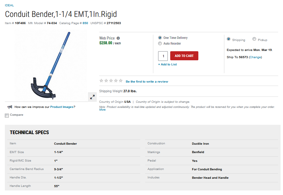
I frequently shop at Grainger and they often list the center-to-center bend radius in their product description (example below).
As far as non-standard angles. Just go to the BendRadiusVersion tab and change the angle value in the table header to anything you want.
Again, thanks for helping me out.
mark
Hello,
I'm very late to the game, but could you walk through that final shrinkage formula? My trig skills are very rusty and I'm a little lost.
I can track on the initial one ignoring bend radius, however I'm mostly not sure why you're augmenting the bend offset in the (BO -4*R) section.
I assume this is also why we're adding the arc lengths back in at the end of the formula
can you explain the steps for S=CL-blue-blue-green to get to the formula S=Cl-HL. I have problems to reduce it, Thanks
Hi Ralph,
Sorry I was not clearer. I use a computer algebra system to do my derivations and I let it handle a lot of the details. Hopefully the derivation I attach here will help. If not, ask another question.
biegert
Your reply was very helpful to understand how to simplify the formula. Thanks for your respond
No problem. I will try to get a clearer derivation in the main article body. Thanks for your comment, which will help me make a better article. I probably will be putting together a web calculator for this calculation because I have had so many people download the Excel workbook. This will make the work more accessible.
biegert
Hi Skyler,
Sorry I was so late getting back to you. Life diverted me for a couple of years (career change, death of a parent, birth of a granddaughter, etc).
Hopefully, the derivation included here helps. If not, ask again.
biegert
Thank you for your efforts for the mathematical details in pipe bending. I would point out a typo In Fig 6 for the first calculation of SL. You wrote Cotangent instead of Cosecant, but it was correct in the next equation for CL.
All bets are off if you don't have the right bend radius. I will be using an Ideal 1" EMT bender. It gives 8" for the circumference of a 90 deg bend, which comes out to 5.04" radius. You show (Fig 7b) an Ideal bender as having a radius of 5.25" (inner radius+1-1/8/2 for the centerline radius), but don't identify it (has to be the 1" tool). You show the technical specs for the 1-1/4" bender, but I just can't find any technical specs for the 1" bender! Not really your problem, but it's making me crazy. Guess I'm just going to have to bend some pipe and find out!
I'm going to be doing some out-of-plane bends, so I'd like to be able to make some calculations, and I'm a mechanical engineer, so that explains a lot. Understanding the equations helps translate the how-to YouTube videos, so thanks again for your work!
Thanks for pointing out the typo. I always appreciate folks helping me with quality control. This may explain a couple of derivation questions I received.
I have not looked at an enormous number of conduit benders – just the ones carried by the BORG (Big Orange Retail Giant).
I am in the process of pulling together a Javascript online calculator that should work well on a phone. When I originally wrote this post, I was deep into Excel. One semi-interesting sidelight is that I wrote this post after I had done some analysis of WW2 torpedo fire control computers. It turns out the math used for firing straight-running torpedoes is almost identical to conduit bending:
Kind of similar to bending conduit.
mark
An offset and a right triangle are two different shapes, they take different math formulas to solve.
A right triangle is three straight lines.
An offset is one straight line and two arcs.
If you want to solve a circle you do not superimpose a square on the circle and use the square's formulas to solve the circle.
There is an app called Bend Aid that solves the correct math formulas for the shapes that conduit can be bent into.
https://conduitbendaid.com
Wow!! you really dont know your stuff