Introduction
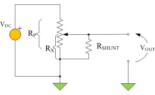
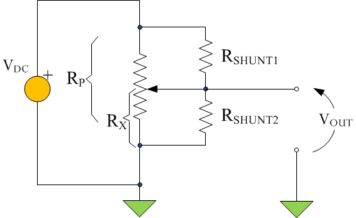
While I was looking for different circuits that generate a logarithmic characteristic (voltage, current, or resistance), I stumbled upon a web page that discussed a logarithmic potentiometer approximation using a linear potentiometer with one or two resistors connected to the wiper as shown in Figures 1 and 2. Note that this potentiometer characteristic is actually exponential -- why this nomenclature inconsistency has developed is beyond me.
As I continued hunting, I found an excellent article that describes creating a Verilog model for the same circuit using Qucs (a circuit simulator that I like).
My goal here is to create a circuit that produces an output voltage that is related approximately to a exponential function with the wiper position as the argument (wiper position is expressed as a percentage of its full scale movement). My plan here is to use Mathcad to pick values for the resistors in both circuits that minimizes the maximum error of the logarithmic approximation.
One-Resistor Version
Figure 3 shows the results of my analysis of Figure 1. There is nothing special here as far as analysis goes. The results do indicate that the one-resistor circuit of Figure 1 produces a relatively poor result.
Two-Resistor Version
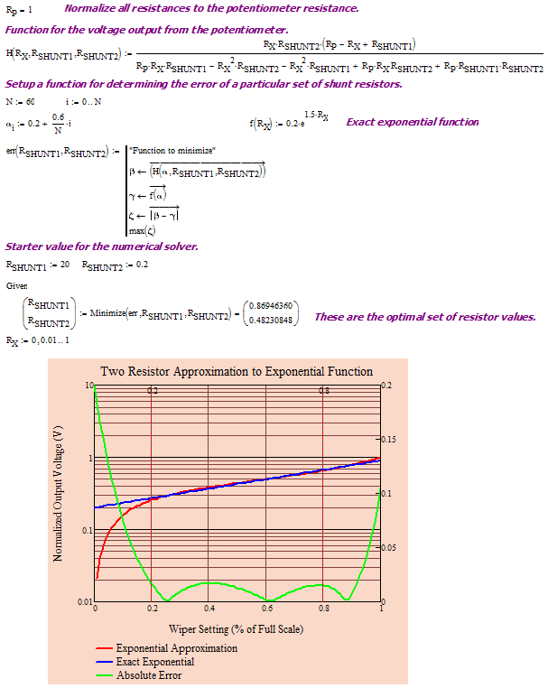
Figure 4 shows the results of my analysis of Figure 2. The results indicate that the two-resistor circuit of Figure 2 produces a relatively good result for wiper positions of 20% to 80%. I could see me using this approximation for some applications.
Conclusion
I included this post for completeness. I wanted to store away all the exponential circuit approximations that I found into a searchable database. See the Appendix for empirical results.
Appendix
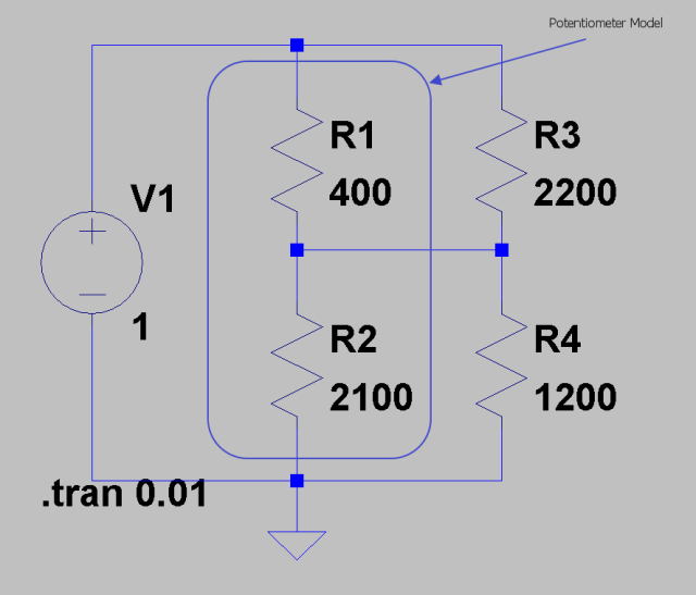
Figure 5 shows the circuit as I have it in LT Spice.
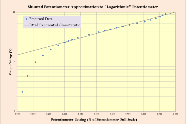
Figure 6 shows the empirical test data. Not too bad.


Pingback: Some Empirical Potentiometer Results | Math Encounters Blog