
Introduction
I have had several people say that my house number is difficult to read at night. The number consists of four digits mounted on a structural column that holds up a section of my roof. In response to these complaints, my wife has asked that we install some sort of light for our house number. She was thinking we get someone like Aardvark Electric, Inc. (for light fixture installation) to do it but I thought it would make for an excellent project and blog post. Plus the structural column was rotting and needed to be replaced, I decided that it was a good time to replace the column as well whilst I lit up the house number.
Unfortunately, I could not find a light fixture that she liked, so I decided to build one from scratch. This blog post is about how I built the light. This was not a huge project, but it did involve me learning a bit about designing with phototransistors.
Requirements
My requirements are simple:
- All wiring is low-voltage.
I do not like running AC outdoors. I do not need an AC circuit to power a few LEDs.
- I want the house numbers lit directly -- no side lighting.
Some quick experiments showed that side lighting creates nasty shadows that makes the numbers hard to read.
- The light enclosure must be made of cedar.
This requirement comes from my wife. The structural column was not pretty. On the prompting of my wife, I clad the column in cedar. My wife likes the cedar and she was wondering if I could make the light enclosure out of cedar.
- I will not use any cadmium.
When I was a boy, I would have used a cadmium sulfide cell to sense the light level. Today, the toxicity of cadmium is well known and it is banned from any electronics that I design today. I take "green" design very seriously.
- I will use LEDs for lighting.
I like LEDs because they are energy efficient, run cool and I do not want anything hot in a cedar box. Even Neon Lights you see for a shop front or christmas decoration uses LEDs these days. If I need to install or replace any more lights in future I know what type to get.
- I am only building one unit.
Designing for production requires more than a weekend, which is all the time I have.
- The light will turn on at sundown and off at sunup.
The light is not needed during the day. We need to define what we mean by the light level at sundown and sunup. The Wikipedia describes the sunup/sundown light level as 400 lux. The lux is a photometric unit, which means it is defined with respect to the effect of electromagnetic radiation on the human eye. The sensitivity of the human eye varies with the wavelength of the light it is looking at. 400 lux corresponds to 585.6 mW/m at 555 nm. Sunlight has a nominal wavelength of 500 nm. Using the chart shown on this web page, we can see that the eye's sensitivity at 500 nm is pretty close to its sensitivity at 555 nm. So I will assume that sunlight at 400 lux can be modeled using a light power density of 585.6 mW/m at 500 nm. The results will be close enough.
Finished Project
Rather than wait until the end of this post, I will show you how everything ended up. Figure 1 shows the final product. Remember -- I am an amateur woodworker who threw this together on a weekend. However, my wife likes it and that is good enough for me.

Figure 1: My Light with Annotations.
Circuit Design
Figure 2 shows the circuit, which I captured in Kicad -- an open-source schematic/PCB layout tool. I used a simple comparator circuit to turn the light on at night. During daytime, the phototransistor is conducting, the comparator output is high, and the LEDs are off. When it is dark, the phototransistor is not conducting and the comparator output is low and the LEDs are on.
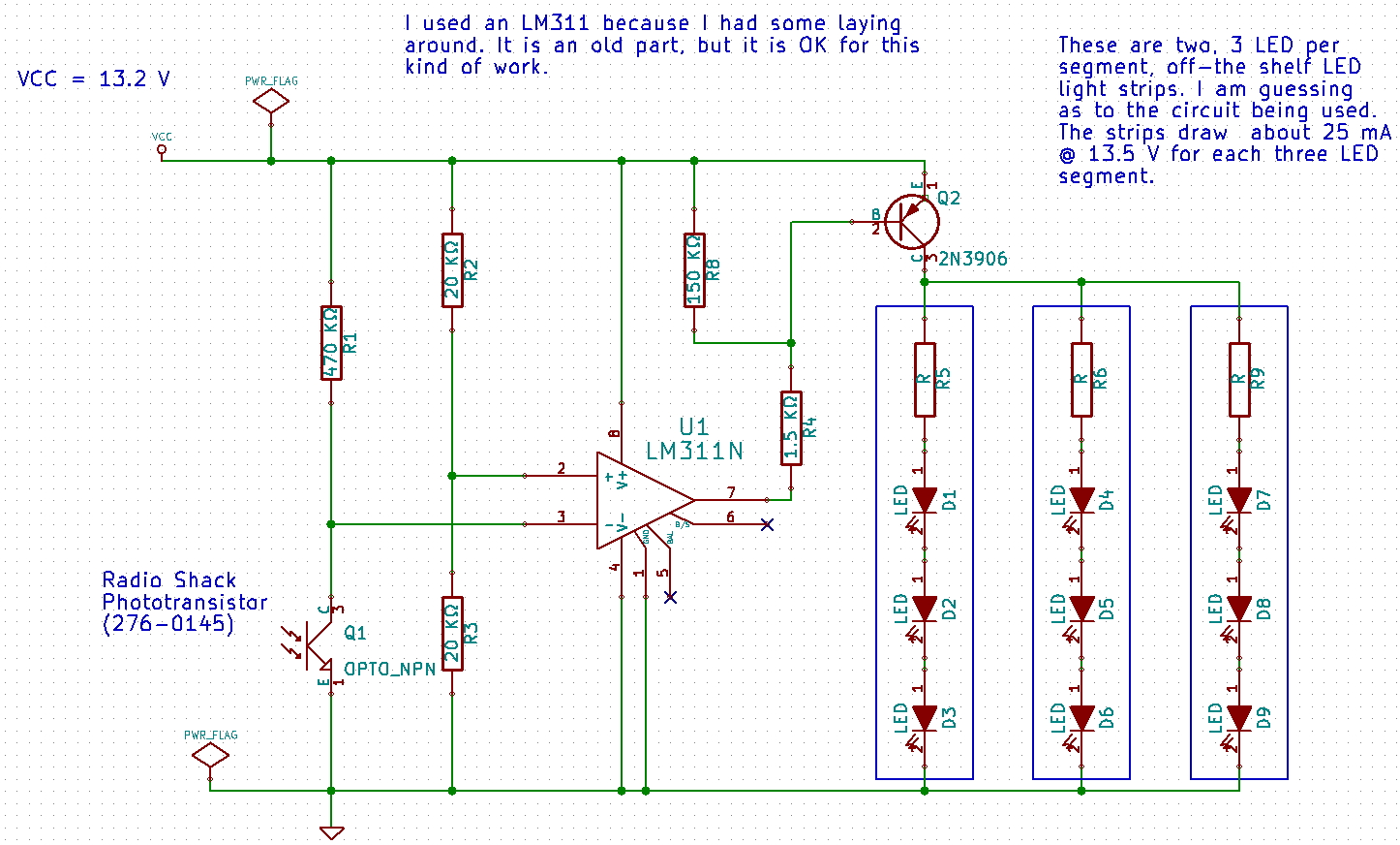
Figure 2: Schematic of My Light Sensor.
If I had more time, I would have added some hysteresis to the circuit. However, I am seeing no issues at this point, and I will just leave the circuit as it is. For the details on how I determined the values of R4 and R8, see Appendix A.
Project Design Elements
Mechanical Design
I designed the enclosure using Solidworks. This link provides an eDrawing of my design. Most folks do not have an eDrawing reader installed, but this reader is becoming the "Adobe Reader" of 3D mechanical design. I have a translucent plastic cover over the lamp that diffuses the light and ensures that we do not have to gaze upon bright LEDs. I found my plastic cover here , and I was amazed at all the options available.
Light Source
I started my project by looking for some LED strip lightning. Figure 3 shows a sample of the different kinds of strip lighting that I found. I chose the SMD3528, which I have enclosed in a red rectangle in Figure 3.

Figure 3: LED Strip Lighting Examples.
Figure 4 shows a closeup of the LED light strip that I bought.

Figure 4: Closeup of the Strip Lighting that I Finally Bought.
Figure 5 shows the only specifications that I could find for the LED strip.

Figure 5: Specifications for the SMD3528 LED Strip.
As shown in Figure 5, the strips are specified to draw 20 mA per 3 LED segment. I actually measured 25 mA per 3 LED segment.
Phototransistor
Specifications
A phototransistor is basically a transistor with a package that allows light of some wavelength to penetrate right down to the silicon. It turns out that many transistors are light-sensitive. I have even heard of people exposing the die of a 2N2222 transistor and using that as a phototransistor. One common difference from a normal three-terminal device is that many phototransistors only have two terminals (emitter and collector) because the light generates the base current. There are three-terminal phototransistors and they allow you to connect up a base resistor to control the sensitivity of the device. I only had a two-terminal phototransistor laying around.
I have some Radio Shack parts laying around the house, including a phototransistor (RS Part Number 276-0145). The only specifications I could find for this part were on the web and are shown in Figure 6.

Figure 6: Rough Specification for the Radio Shack 276-0145 Phototransistor
From a design standpoint, the key specification is for the "light current," which is a parameter that relates collector current to the incident light power density.
| Eq. 1 |  |
where
- IC is the phototransistor collector current (in mA).
- PLight is the input optical power level @ 500nm (= 585.6 mW/cm ).
- γ880nm is the collector current to light power density level (=20 mA/(20 mW/m ) @ 880 nm - my assumed wavelength of maximum sensitivity for an infrared phototransistor).
- S500nm/880nm is the sensitivity correction from the phototransistor's reference level to the average sunlight wavelength of 500 nm (= 17%, Figure 7).
- IDark is the phototransistor dark current (100 nA, specification).
Phototransistor Sensitivity Versus Wavelength
The Radio Shack phototransistor is target for infrared applications, like television remotes. However, these phototransistors can detect visible light, albeit with less sensitivity than infrared light. Unfortunately, the Radio Shack part specification does not state its sensitivity as a function of wavelength. I found a specification for a similar part from Vishay (BPV11) that does include this information. Figure 9 shows the BPV11's sensitivity versus wavelength and I will assume the Radio Shack phototransistor has the same wavelength dependence.

Figure 7: BPV11 Phototransistor Sensitivity Versus Light Wavelength.
I now have enough information to complete the design the circuit.
Selection of Resistor R1
The only component that requires some design work is R1 (see Figure 1). I have set the comparator to trigger when the voltage drop across R1 is one half the supply voltage (= 13.2 V/2 = 6.6 V). The calculation is shown in Figure 8.

Figure 8: Calculation of R1 Value.
The ideal value for R1 would be 656 kΩ. I do not have that resistor value laying around, but I do have 470 kΩ. While a little low in value, it just means that light will turn off and on when it is a bit lighter out than 400 lux -- no big deal.
Conclusion
I built the circuit and it turns on at sunset (9:00 PM at 45 latitude one week after the summer solstice). My wife is happy -- I am happy.
Appendix A:Calculation of R4 and R8
Figure 9 shows how I derived the resistor values for driving transistor Q2.

Figure 9: R4 and R8 Resistor Value Derivations.
I assume the LM311 has an OC output? If so, you might want to connect an R(be) to deal with any output leakage current...
The LM311 does have an open-collector output. If I would have had more time, I would have added a number of things. An Rbe would have been a good thing to add. Some additional hysteresis would also have been a good thing.
You could not believe the weekend I had. I had to dig a trench to bring in the low-voltage as well. I did not discuss it in the blog post, but there was a water feature involved in this effort too. And tree planting.
Mathscinotes
P.S. I did add an Rbe to the design and its implementation in my light. It is still working after all these years.
I see WC leakage over temp is 0.5µA, so your transistor (<a mW) is safe (and your house too). I'll sleep better. Hysteresis would be a good thing, yes 🙂 Esp. if the photoxstr sees any of the LED light!
I'd be happy for a productive weekend like that 🙂
What do you think of Kicad? Have you compared it to gEDA?
I have been using Kicad now for a couple of years. I have not tried gEDA. I have done a couple of Kicad-based PCB designs and a large number of breadboard projects with it. I have one large PCB project in process at the moment. I must say that I like the hierarchical design support and I use the online router all the time.
So I like it. It has some annoying characteristics -- I wish the keyboard shortcuts were more consistent with other tools. Some folks are just beginning to put together a scripting package for it, and I plan to experiment with that soon.
Hope all is well with you.
Mathscinotes