
Quote of the Day
The worst enemy of life, freedom and the common decencies is total anarchy; their second worst enemy is total efficiency.
— Aldous Huxley
Introduction

Figure 1: Trapezoidal Specification Example. (Source)
Sinusoids hold a revered place in electrical engineering -- they should. However, I do encounter quite a few trapezoids in telecom power systems. During a meeting the other day, I was asked "Why do we use trapezoidal waveforms for Alternating Current (AC) signals like ringer voltages and remote power systems." It was a good question. I have written about the trapezoidal waveform before, but I have never explained why the trapezoid is used so frequently.
As with most engineering tradeoffs, our constant quest for lower cost at a specified level of performance will drive the answer. Let's dig in ...
Background
Assumptions
To simplify this discussion, I will assume that we are evaluating the relative merits of two types of AC power system output waveforms, sinusoidal and trapezoidal. Figure 2 shows my simple model for a trapezoidal power system. The sinusoidal model is identical except for replacing the trapezoidal waveform with a sinusoidal waveform.

Figure 2: Trapezoidal Power System Model.
The choice of power source waveform will have an impact on the load power converter's cost. Because there are far more loads in telecom systems than sources, the total system cost is usually driven by the cost of the load hardware. Thus, it is important to choose a power source waveform that will reduce the cost of the load's power converter.
I am going to ignore any cost differences in generating trapezoids versus sinusoids. The Total Cost of Ownership (TCO) for the system is dominated by the large number of loads, so a bit more cost in the generator is more than made up by the lower cost of the loads.
Key Idea
The TCO for power conversion systems is driven by their installed cost, operating efficiency, and failure rate. Systems that have high peak currents relative to their RMS input currents have a higher TCO than systems with lower peak to RMS input current ratio. The ratio of peak to RMS current is called the Crest Factor (CF). While I will focus on the CF for currents here, similar statements can be made for voltages as well. I focus on the current CF here because it is larger than the voltage CF. Power systems with diodes in them tend to see high current peaks because of the exponential dependence of diode current on diode voltage.
I can give you a number of examples as to why high CF drives system cost:
- Capacitor Reliability
The reliability of aluminum electrolytic capacitors are reduced when they must support large ripple voltages. High CF tends to create high ripple voltages across these capacitors.
- Conversion Efficiency
Systems with high CF have relatively high peak currents, which also results in RMS currents that are significantly higher than the average current draw. High RMS currents increase resistive losses in teh system, making the overall conversion efficiency lower. The lower conversion efficiency increases the total cost of ownership of the system by driving up annual operating costs.
- Power Dissipation
Power dissipation increases the load's operating temperature, which results in lower reliability.
- Component Cost
The cost of many components, like diodes, is driven by the peak current they must handle.
Ideally, we want to choose the voltage waveform that will minimize the CF level. The trapezoidal waveform is easy to generate and reduces the CF level in the system.
Some Definitions
We need to provide some precise definitions of the following terms.
- Crest Factor (CF)
- The crest factor is a waveform metric that is calculated from the peak amplitude of the waveform divided by the RMS value of the waveform. Mathematically, we compute crest factor using
, where f represents the waveform. We can compute CF for either current or voltage. In this note, I focus on currents.
- Peak Current (
)
- Peak current is the maximum current at which the product must meet its requirements.
- Peak Voltage (
)
- Peak voltage is the maximum voltage at which the product must meet its requirements.
- Root-Mean-Square (RMS)
- The RMS value of continuous-time parameter is the square root of the arithmetic mean of the square of the function that defines the continuous parameter. Mathematically, we compute the RMS value using
, where f(t) is the continuous-time parameter (usually voltage or current). The RMS value of a waveform is always greater than or equal to its average. The proof is here.
Analysis
Rectified Input Characteristics
Most telecom loads use some form of bridge rectifier at their power input. Figure 3 shows a typical example.

Figure 3: Rectified Output Voltage.
The rectification process causes the input current draw to appear in the form of spikes that occur when the input waveform is at its peak. The input spikes occur because the input only draws current when the input voltage is higher than the voltage on the output capacitor. I found a couple of nice illustrations of this action on this web site and I repeat them here in Figure 4.
 |
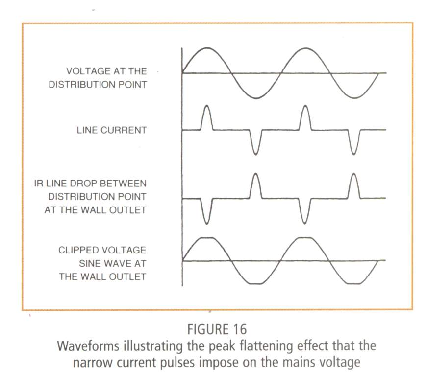 |
| Illustration of the Input Current Draw Spikes | Input Current Draw and it Effect on the Input Waveform. |
Example Circuit
Rather than use mathematics to beat this problem to death, I thought I would just perform a simulation. I downloaded the free simulator LTspice and put in a simple example circuit. This circuit is completely made up just for use in this example, so do not send me email telling me that there are better components I could use.
Figure 5 shows the LTspice simulation for the case of a sinusoidal input (10 V amplitude at 100 Hz). The circuit has a 0.5 mA current source for its output load.

Figure 5: Simulation Schematic for a Sinusoidal Input Voltage.
Figure 6 shows the LTspice simulation for the case of a trapezoidal input (10 V amplitude at 100 Hz). The circuit has a 0.5 mA current source for its output load.

Figure 6: Schematic Configured for a Trapezoidal Input Voltage.
Simulation Results
Figure 7 shows the simulation results for the sinusoidal test case. Notice that the input current peaks at ~3.3 mA even though the actual output current is only 0.5 mA.
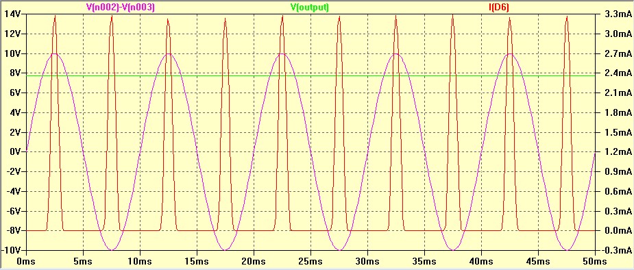
Figure 7: Simulation of the Rectifier Circuit with a Sinusoidal Input.
Figure 8 shows the simulation results for the trapezoidal test case. Notice that the input current peaks at ~0.820 mA, which is much less than the 3.3 mA peak for the sinusoidal test case.
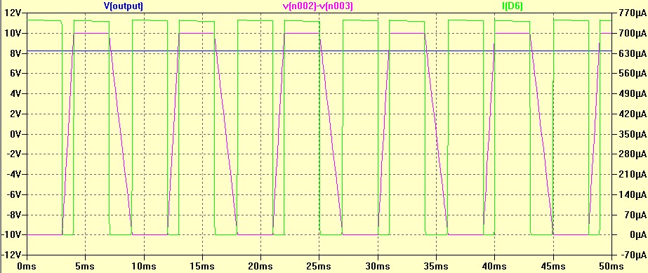
Figure 8: Simulation of the Rectifier Circuit with a Trapezoidal Input.
Conclusion
Table 1 summarizes the results from my simulation effort. The actual calculations are a tad boring, but I have captured them in Appendices A and B.
| Waveform Type | Average Input Current (mA) | RMS Input Current (mA) | Peak Input Current (mA) | Crest Factor |
| Sinusoidal | 0.500 | 1.105 | 3.244 | 2.936 |
| Trapezoidal | 0.500 | 0.575 | 0.743 | 1.293 |
We can see from Table 1 that the crest factor is much lower for a trapezoidal input signal than for a sinusoidal input signal. This means the the cost of component can be minimized and the overall reliability improved if we use a trapezoidal waveform for our AC voltage waveform.
Appendix A: Average, RMS, and Peak Current Values for the Sinusoidal Input Waveform.
Figure 9 shows an example of basic sine wave current calculations.

Figure 9: Screenshot of Mathcad Worksheet Calculations for Average, RMS, and Peak Input Current Using a Sinusoidal Input Waveform.
Appendix B: RMS and Peak Current Values for the Trapezoidal Input Waveform.
Figure 10 is similar to Figure 9, but for a trapezoidal waveform.

Figure 10: Screenshot of Mathcad Worksheet for RMS and Peak Current Using a Trapezoidal Input Waveform.
This is great information. I was wondering- do you know how they generate a trapezoidal waveform? What power levels are typical ?
There are all sorts of ways to generate a trapezoid. In phone ringer systems, they are low-power (~3 W) and you can easily generate a triangular waveform using a current sources and a capacitor. To generate a triangular waveform, drive a positive current into a cap for a period of time, then the same value of negative current for the same amount of time. Take that triangular drive and use it for the input to an amplifier that clips.
High power systems do exist (kW range) and these normally just switch off and on. They may have a trapezoidal shape just because the output stage has a rise and fall time. See this post for an example.
mathscinotes
I have buy home UPS of Microtek 1600 VA/24V with two tubeler battery, UPS waveform is TPZi waveform ( TRAPE ZOIDAL WAVEFORM) . My frnds tell me Sine wave UPS is better than this , so i confuse so please give solutions ,. What's bad effects on demostic equipments ..!
The main concern I have with trapezoidal waveforms is the electrical noise they generate. The only actual failures I have had with trapezoidal power have been with radios. They electrical noise in one or two cases has been so bad that I could not listen to the radios.
mark
It is common to call a trapazoidal waveform a square wave. What parameters exist to define a waveform as a trapazoid?
One person's square wave is another person's trapezoid – I would argue all "square" waves are really trapezoids because edge rates are always finite. I work in telecom, where we often use trapezoids – mainly for the ringing wave shape in telephone circuits. We distinguish between trapezoids by crest factor or edge rate. Any signal with a rise/fall time faster than an arbitrary limit would be considered square. The following figure shows how a trapezoid is specified in Si3220 SLIC specification.
There are codified standards (e.g. TR-57) that call out trapezoids as acceptable ring wave shapes and differentiate between them by crest factor. The following figure shows an example from the telephony section of the SBV5322.
There are also AC power supply standards that also support trapezoids rather than sinusoids because the trapezoids are easier to generate.
Mark
Why trapezoidal waveform produce more torque than sine wave in a DC motor?