
Introduction
Today I'm going to be discussing ethernet cables and if you've been reading this blog for a while, you know I'm no stranger to ethernet problems. I work with it quite a lot at work so I'm familiar with products like the ws-c2960s-48lps-l cisco catalyst and all the cables that ethernet entails. I am looking at category 5e (cat5e) cabling today. During some routine testing, I was seeing bit errors occurring on 100 meter long Ethernet cables that were operating at 60°C. This prompted me to investigate the effect of temperature on Ethernet bit error rate. Some businesses use a host server such as Hostiserver to minimise any faults and improve their web experiences. I found it surprising how complicated doing design work with these cables can be. In this post, I am going to review some basic cable characteristics and the kind of things that engineers need to look at when designing networks using these cables. There is nothing earth-shattering in this discussion -- things are just more complicated than you might expect. Let's dig in ...
Background
What Limits Cable Reach?
Most people think that the reach of Ethernet is 100 meters -- at true statement for a system operating at 20°C. We usually do not discuss what limits the reach of the cable. For the discussion at hand today, I will assume that signal attenuation limits the reach of the cable. There are other factors that can limit the reach of a system, but for today we will only look at signal attenuation.
The 100 meter reach number is based on some assumptions:
- 90 meters of cat5e cable
Cat5e cable is composed of 4 pairs of 24 American Wire Gauge (AWG) solid wires (8 wires total). The pairs are twisted to reduce the effects of electromagnetic interface. Unfortunately, the signal attenuates as it travels down the cable. The amount of attenuation is referred to as insertion loss.
- 10 meters of cat5e patch cables
Cat5e patch cables are composed of 4 pairs of 24 AWG stranded wires (8 wires total). The stranded wire is more flexible and is easier to bend than solid core wire, but it has higher insertion loss.
- 4 connectors
Connectors introduce additional losses that must be accounted for.
Communication systems are composed of transmitters, channels, and receivers. A minimum requirement for a reliable communication systems is for the transmitters to send a signal that is large enough for the receiver to clearly interpret after being attenuated by the channel.
Cat5e Attenuation Limits
The cat5e cable and connector attenuation limits are set by the industry standard TIA-EIA-568-B.2. I repeat these limits in Equation 1.
| Eq. 1 |  |
 |
|
 |
where
- IL100mCable is the insertion loss introduced by the 100 meters of cat5e cable (solid wire) at 20 °C.
- IL100mPatchCable is the insertion loss introduced by the 100 meters of cat5e patch cable (stranded wire) at 20 °C.
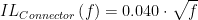
- ILConnector is the insertion loss introduced by a single connector at 20 °C.
- f is the signal frequency expressed in MHz.
The industry has taken the approach that, as long as a cable has less attenuation than the specification's limit, enough signal from the transmitter will get through the channel to the receiver for reliable reception. Reliable reception is defined as a Bit Error Rate (BER) less than 1E-10.
Analysis
Insertion Loss @ 20 °C
Figure 1 shows a screenshot of the Mathcad worksheet that I am using for my analysis. I have duplicated the insertion loss chart of TIA/EIA-568-B.1.
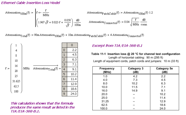
Figure 1: 100 meter Cat5e Insertion Loss Calculation.
Insertion Loss Increase at Higher Temperature
TIA-EIA-568-B-1 specifies how the insertion loss calculations are to be performed at elevated temperatures. Cable loss is to modeled as a 0.4% per °C increase in temperature. For the exact quote, see Appendix B. Since all the losses are multiplied by 0.4%/°C and we must keep the insertion loss under the 20 °C value at all frequencies, the maximum reach of Ethernet reduces by 0.4%/°C. So if we run our Ethernet over 60 °C cable, the maximum range is reduced by 16 meters. The calculation is shown in Equation 2.
| Eq. 2 |  |
Conclusion
It appears that the increased temperature I am encountering with this cabling is reducing the maximum length supported by Ethernet. I will need to adjust my test configurations.
Appendix A: Quote on Stranded Cable Insertion Loss Tax
The following quote from TIA-EIA-568-B-1 addresses the modeling approach to be used for cat5e patch cables.
Cat 5e stranded cable table shall meet the values computed by multiplying the horizontal cable insertion loss requirement in clause 4.3.4.7 by a factor of 1.2 (the de-rating factor), for all frequencies from 1 MHz to 100 MHz. The de-rating factor is to allow a 20% increase in insertion loss for stranded construction and design differences.
Appendix B: Quote on Cat5e Insertion Loss Increase with Temperature
The following quote from TIA-EIA-568-B-1 addresses the modeling approach to be used for cat5e patch cables.
Insertion loss is expressed in dB relative to the received signal level. Insertion loss shall be measured for all cable pairs in accordance with ASTM D4566 and 4.3.4.14 at 20 ± 3°C or corrected to a temperature of 20 °C using a 0.4%/°C correction factor for category 5e cables for the measured insertion loss.
Thanks for the great info. It appears you really know your stuff when it comes to network cabling.
Really an informative post... Come to know about much knowledgeable thing regarding network cables... Thanks for sharing..
What you wrote is correct, cable insertion loss derates as temperature increases, but it is probably not why you have packet loss. PHY vendors test their PHYs in excess of 100m (as much as 140m) to have margin for temperature and connector degradation. What is probably happening is the PVC jacket and insulation (assuming you are using riser cable) as they heat up are causing the characteristic impedance of the cable to decrease, which causes return reflections (echo) to exceed the dynamic range of the echo and next cancellers. Try using outdoor-rated cat5e or cat6 cable. Check the data sheet and make sure the insulation and jacket are polyethylene or polypropylene, which have less impedance variation vs temperature. If this is for a plenum application DO NOT use non-plenum rated cable
Kadir "Solid Gold" Suleyman
Thanks for sharing this great post with us.It is helpful.
Cat5 Phoenix
Excellent article. It shows me that, you really know your stuff when it comes to network cabling. These are very helpful information on networking cable. Thanks for sharing..!! Visit: https://bit.ly/2BiJwty
The coefficients you use for your Equation 1 are wrong. You are using Cat3 k1 for "k1" and Cat5 k1 for "k2". You show the correct coefficients in your MathCad screen shot.
Thanks. I will correct.