
Hell, there are no rules here - we're trying to accomplish something.
Introduction

Figure 1: Fiber-Optic Cable Being Hooked Up To
A Shore Facility. (Source)
I am at the Optical Fiber Conference in Los Angeles this week and learning a lot. For example, this morning I attended a great talk submarine fiber optic cables given by Neal Bergano, CTO of TE Connectivity Subcom. I thought I would put my mental notes on a post for others to view. I was not able to find a copy of Neal's presentation, so I just recalled what I could. Where possible, I will include supporting information that I located on the web. Any errors introduced are mine.
If you are interested, I have discussed these cables in other posts (here and here), but not at this level of detail.
Fun Submarine Fiber-Optic Cable Facts
- All the continents but Antarctica are connected by fiber optic cables.
Figure 2 shows how extensive the world's network of submarine fiber optic cables has become (source).

Figure 2: World Fiber Optic Deployments.
- 99% of the world's transoceanic traffic goes over submarine cables.
He said that no one knows what the real number is. It could be 99.999%, but people hedge their bets by saying 99%.
- Submarine Fiber-Optic Cables Include Power Amplifiers, Gain Equalizers, and Branching Units.
Submarine cable systems include more than just fiber. They also include the following "bumps" in the cable:
-
- Repeaters (Erbium-Doped Fiber Amplifier [EDFA]) to restore signals levels lost because of attenuation over distance.
My web research shows the repeaters are placed every 60 km or so.
- Gain Equalizers to ensure all wavelengths (i.e. colors) are maintained at the same level on the fiber.
Each wavelength experiences different losses on the fiber. The equalizer will introduce different levels of amplification for each wavelength to make their power levels equal.
- Branching Units for connecting sites far from the main fiber ring.
If you look carefully at Iceland on Figure 2, you can see a branching unit was used to provide a connection. In the SONET world, you would also call a branching unit an add-drop mux.
- Repeaters (Erbium-Doped Fiber Amplifier [EDFA]) to restore signals levels lost because of attenuation over distance.
Figures 3(a)-(c) show pictures of each of these items (source).


Figure 3(a): Photograph of Fiber Repeater. Figure 3(b): Photograph of Gain Equalizer. Figure 3(C): Photograph of branching unit. Figure 4 illustrates how repeaters, equalizers, and branches are combined in an actual deployment (source).

Figure 4: Illustration of a Submarine Fiber-Optic Cable Deployment.
-
- Power is fed to the submarine cable by DC current sources at both ends of the cable with the seawater providing the return path.
Figure 5(a) shows block diagram from this paper that illustrates the sea water ground (source). Figure 5(b) illustrates how both sides of the fiber have opposite potentials applied, with X equaling the total voltage drop across the cable.


Figure 5(a): Block Diagram of Both Ends of the Submarine Cable. Figure 5(b): Graphic Illustrating Opposite Ends of the Cable Have Opposite Potentials Applied. I saw in this article that 95% of damage to submarine fiber optic cables is due to fishing operations. I also often read about dragged anchors breaking fiber-optic cables.
- Submarine Cable Types Vary with the Level of Protection Required.
The deeper you go, the less armor protection you need to have. So deep water cables need minimal protection. Figure 6 illustrates the use of different cable types.

Figure 6: Illustration of Using Different Types of Fiber-Optic Cable.
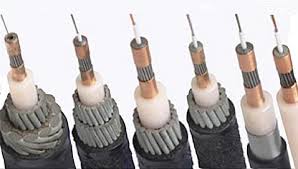
Figures 7(a) and 7(b) show the level of fiber armor that is available. Fiber-optic cable for deep water has a size comparable to a standard garden hose (17 mm to 22 mm diameter). The armored cables can be as large as 50 mm.


Figure 7(a): Different Levels of Armor Are Used Depending on How Vulnerable the Cable is to Damage. Figure 7(b): Cross-Section of Different Types of Submarine Cables. - Shallow water cables may need so much protection that they also must be buried.
Figure 8(a) illustrates how towed underwater plows can be used to bury cables on the sea bottom. Figure 8(b) shows a plow that can bury a fiber optic cable 2 meters under the sea bottom.


Figure 8(a): Illustration Showing How Fiber is Buried By an Underwater Plow. Figure 8(b): Picture of Underwater Plow. - Video illustrating how a cable-laying ship deploys fiber.
These are large ships are there are multiple of them working on the ocean.
Besides laying new cable for telecommunications and fishing up old ones for repair, these ships also are busy laying fiber for sensor networks. Here is an example of a submarine fiber network, called Neptune, that services seismic sensors just off the coast of the state of Washington and British Columbia (Figure 9).

Figure 9: Project Neptune Seismic Surveillance Network.


Numerical Example
The presentation included a rough numerical example (Figure 10) of how power is fed to the cable. I am recalling this stuff from memory, but I think this is close to what was presented. I added some information about the number and power use of the repeaters because that subject interests me.
The key points of this numerical example are:
- The voltage is very high (~10 kV)
- The power is really not that high (~10 kW)
- The distances can be enormous (thousands of kilometers)

Figure 10: Rough Power Feed Calculations.
One interesting aspect of the calculation is that a large ground difference must be accommodated between the continents. It turns out that ground level between the continents is normally low (I do not recall what low value was mentioned), but that it can get quite large (~1000 V) during geomagnetic storms (reference).
Conclusion
Sorry for the rambling nature of the post, but it represents my recollections from the talk. I wanted to make sure I wrote down the information because it was interesting.
Appendix A: Submarine Cable Power Feed Characteristics
Figure 11 shows some key specifications for a submarine cable power feed system (source).

Figure 11: Key Submarine Cable Power Feed Characteristics.
Appendix B: Submarine Cable Repeater Characteristics
Figure 12 shows some key specifications for a submarine cable repeater (source).

Figure 12: Key Repeater Characteristics.
Pingback: Daily Tree Consumption for Toilet Paper | Math Encounters Blog
Very Good article