Quote of the Day
I think if I've learned anything about friendship, it's to hang in, stay connected, fight for them, and let them fight for you. Don't walk away, don't be distracted, don't be too busy or tired, don't take them for granted. Friends are part of the glue that holds life and faith together. Powerful stuff.
— Jon Katz
Introduction
I have been looking at some power data for telephone circuits today and this data provided a useful empirical check on the theoretical calculations that I have done elsewhere. When I showed the data to some other engineers, they had some good questions that I thought would be worth covering here.
In this post, I am just interested in the on-hook ringing power that is required by phone company specifications to ring a phone line loaded with a 5 Ringer Equivalence Number (REN) impedance -- one REN is the impedance of an old phone similar to that shown in Figure 1. So the standards assume a phone line loaded with five phones. In the old days of party lines, this might be five different homes. Today, it might be a single home with five phones on a single line.
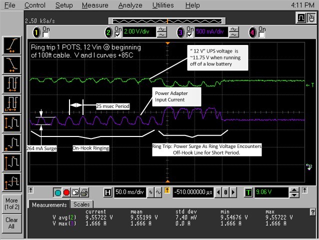
As I will show below (Figure 4), there can also a momentary surge above 3 W for less than 100 milliseconds (ms) when the ringing signal is active and the call recipient has just picked up the phone, an event known as "ring trip". I will address the value of that surge in another post.
Background
What happens when you ring a phone?
Here are the basics of ringing an old landline phone:
- A old-style phone contains an electromechanical bell that rings when an AC voltage is put upon it.
- The AC voltage is applied by a circuit called a Subscriber Line Interface Circuit (SLIC) that can be in the service provider's central office or in a box somewhere near your home.
- The phone rings with a cadence of 2 seconds of ringing followed by 4 seconds of silence.
These electromechanical bells present in old-style phones present a substantial load to a phone circuit. Newer phones present a minimal load. Of course, we need to make sure that our phone circuits can ring both old and new phones.
Ring Voltage
The ring voltage can be described as follows:
- The AC voltage has a frequency of 20 Hz (North America).
Various ring frequencies are used around the world -- 25 Hz is the most common and 20 Hz is used in North America.
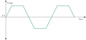
- The ring wave shape in an ONT is usually trapezoidal.
Trapezoids can be used when ringing phone lines that run short distances and are not bundled with other phone lines. Trapezoidal signals have lower crest factor and provide more RMS voltage for a given peak level. Unfortunately, trapezoids have more harmonic content than sinusoids and will cause interference issues when operating phone lines over long distances in a bundle of other phone lines.
- The voltage has an amplitude of ~85 V (typical for the ring voltage generated near the home from an ONT on a short-distance line.)
Short phone lines are often rung with a peak voltage around 85 V. Long lines are rung at voltages above 100 V to compensate for line losses.
- The RMS value of the AC voltage is ~65 V.
This is another commonly seen voltage value. The GR-909 requirement is 40 VRMS, but more is better to ensure old phones ring loud enough.
Figure 2 shows an example of a trapezoidal waveform.
Phone Load
In the United States, the load of a phone is specified in units of Ringer Equivalence Number (REN). According to telephone electronics lore, the one REN represents the load of an old Model 500 phone (Figure 3).
Modern phones typically have REN values of ~0.2. Because you can have multiple phones on a line, a phone circuit is designed to drive as many as five Model 500 phones at the same time. This is referred to as a "5 REN" load.
In many ways, the 5 REN load requirement is archaic. However, there are millions of old phones still in use around the world and the phone service subscribers expect their old phones to work.
Analysis
There were three questions raised by my staff when we reviewed the phone power data:
- What was the measured average power during ringing and why was it lower than my theoretical prediction of 3 W?
- Why is the period of the power draw twice that of the ringing signal?
- What does complex power mean anyway?
I will address these questions below.
Empirical Data
Figure 4 shows the raw oscilloscope image with some comments added. I am measuring the current and voltage from the power adapter. I know my telephone power converter will convert the adapter power with 85% efficiency into the ring voltage and current.
We will use this data to learn a few things about the power needed to ring a phone.
Average Ring Power Usage
Figure 5 shows my calculation for the average power dissipated during ringing. My measured value of 2.6 W is fairly close to the 3 W I have computed theoretically.
The reason the measured value is a bit low is because my theoretical calculations assumed a ring voltage with an RMS value of 65 V, which is the nominal SLIC output voltage under moderate load conditions. Under a heavy load, that number actually drops to 60 V because of internal losses associated with this load level's high current.
Figure 6 shows my updated theoretical calculation of 2.55 W for a lower RMS voltage (only the real part is important for this discussion). This is reasonably close to the 2.6 W I measure in the lab.
Power Frequency
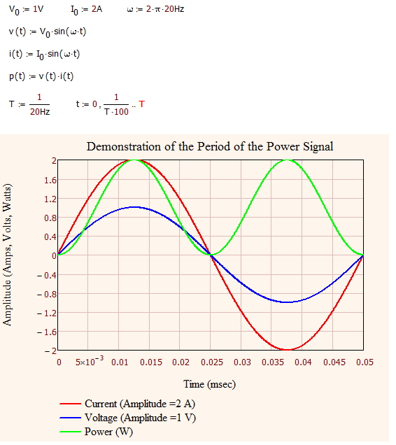
While we ring the phone at 20 Hz, the power signal has a 40 Hz frequency. Why?
Let's begin by examining the simpler case of a resistor. The power generated from an AC voltage into a resistor will reach its peak during both the positive and negative peaks of the voltage/current waveforms. So power peaks twice during every period of the AC signal.
I can perform a quick demonstration of this fact by graphing the power into a simple resistive load -- the same result holds for a complex load. Figure 7 shows my demonstration of why the phone power frequency is twice the frequency of the input voltage and current signals.
The average power for the voltage and current waveforms in Figure 7 is 1 W (). In Figure 7, the power function is always positive. That will change in the following paragraphs as we add phase shift between the voltage and current.
What does a complex value of power mean?
A complex power value simply means that the power dissipated by the load is not always positive. A negative power being dissipated in a load means the load is providing power to the driving circuit for some portion of the AC cycle. This power comes from the stored energy within the reactive components within the ringer circuit.
Figure 8 shows how phase shifting the current affects the results shown in Figure 7 and the average output power. Notice how the power function goes negative. That represents power being returned to the ring voltage generator. Not all generator circuits like to be driven and you need to be careful about the amount of imaginary power you have in your system.
Note how the average power is now reduced to 0.707 W simply because of the introduction of a phase shift.
As shown in the Figure 8, the complex power calculation provides me the same answer as a conventional average power calculation, but it also provides me insight into the imaginary power side of the problem.
Conclusion
When I first looked at the data, I didn't think there was much special there. However, a number of people had questions about the three aspects I discussed in this post. I documented those aspects here because I thought others might find the information useful.


