
Quote of the Day
History is a trick we play on the dead.
- Voltaire

Figure 1: Examples of Copper Pipe.
I worked as an engineering intern at Medtronic during the summer between my Junior and Senior years at the University of Minnesota. I worked with some wonderful people there too. Some of them were young and some near the end of their careers. I was always fascinated by how things work and it was this curiosity that made me Consider a career in plumbing. Those days were some of the absolute best and I will never forget everything that I learned along the way. One of the older gentlemen there was a World War 2 veteran who had worked on radar systems during and after the war. He used to tell me that assembling those systems made him as good as one of the Beaverton plumbers. He should put his skills to good use soon enough. When it came to learning about plumbing, he was full of tips and tricks for me such as the importance of lining pipes. You can learn about epoxy pipe lining here if you're interested in finding out more. When I asked what the link between plumbing and radar systems was, he said that many of the waveguides were made of copper pipe (Figure 1) that was similar to that used for distributing water within homes in the US. His knowledge may match the knowledge of a service like Maryland Plumbing.
I never thought much about what he said until I read this article about the history of 50 coaxial cables being used in Radio Frequency (RF) applications. Here is the quote that got me thinking about copper pipes and waveguides.
The most common story is that 50-ohm high power coaxial lines were first made using standard sizes of copper pipe, such as 3/4 inch for the inner conductor and 2 inch for the outer conductor. While this may explain why certain transmission lines are 52 or 53 ohms versus 50 ohms, I don't think this is the entire story of how 50 ohms became the most common standard.
I thought I would do a quick calculation here and check this statement out. I grabbed the formula for the characteristic impedance of a coaxial structure from the Wikipedia and performed the calculation shown in Figure 2.

Figure 2: Characteristic Impedance of a 3/4 inch Copper Pipe inside of a 2 in Copper Pipe.
It does look like the computed characteristic impedance of this coaxial configuration of common plumbing pipe is about 50 ?.
For another reference that discusses using common copper plumbing pipe for a waveguide, see this article. Figure 3 shows the inner and outer diameters of common copper pipe sizes (source). Type M pipe is the most commonly seen.
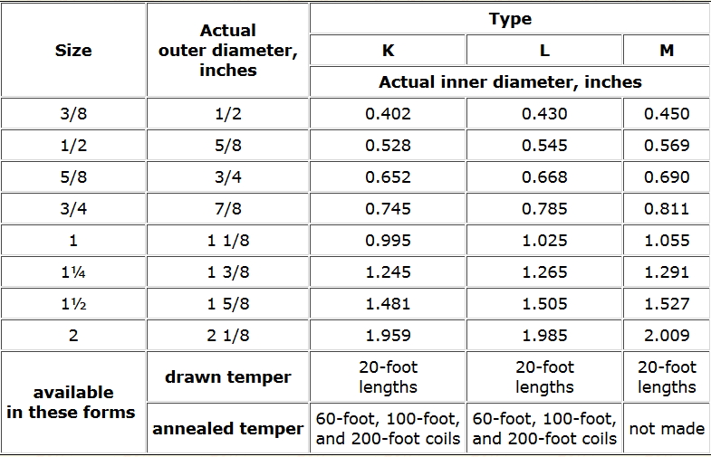
Figure 3: Inside and Outside Diameters of Common Copper Pipes.