
Quote of the Day
Luck usually visits me at 2 am on a cold morning when, red-eyed and bone-weary, I am pouring over law books preparing a case. It never visits me when I am at the cinema, on a golf course or reclining in an easy chair.
— Louis Nizer
Introduction

Figure 1: Example of Machinist's Gage Balls.
Since attending the WMSTR steam show last weekend, I have been thinking about building a steam project. Building a steam project will require some basic machining and I have been brushing up on the subject. I need to decide whether to build something custom (HP made me take a machine shop training course years ago) or assembling a kit. I decide to do a bit of research on machining steam parts and I encountered a paper on measuring the taper of a hole using gage balls. Figure 1 shows an example of gage balls (source).
This was the first time I have seen an application for gage balls and I thought it was worth documenting here. I will derive a formula that I saw in the discussion mentioned above for determining the taper of a hole by determining the depth that two different diameter balls will drop into the hole.
Analysis
Figure 2 shows the diagram I will use to derive the formula. I will need four pieces of information to compute a taper angle.
- R is the diameter of the large gage ball.
- r is the diameter of the small gage ball.
- d1 is the distance from the taper reference to the top of the large ball.
- d2 is the distance from the taper reference to the top of the small ball.

Figure 2: Construction Used to Derive the Taper Formula.
The gage ball diameters are measured by the manufacturer, so I need to make two depth measurements. I can compute the taper by substituting the two depth measurements and the two gage balls radii into Equations 1.
| Eq. 1 | 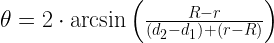 |
We can derive Equation 1 using the approach shown in Figure 3. In the derivation, I equate the length of the of the hypotenuse of the triangle formed by the ball of radius determined two ways: (1) using the half-angle and the radius R, and (2) using the measurements that were taken (d1 and d2).

Figure 3: Derivation of the Taper Formula.
To illustrate the use of Equation 1, I present an example in Figure 4.

Figure 4: Taper Calculation Example.
I show the associated calculations in Figure 5.

Figure 5: Computations For Example in Figure 4.
The formula worked pretty well considering the tolerances involved.
I should comment that handling these small gage balls could be a problem. I did notice that you can buy them with handles, which should make using them easier.
By the way, only one of the gage balls needs to go all the way into the hole. The big one can stick out − this just means that d1 is negative. Here is an example from the discussion mentioned above and how I worked the problem. Note that the gage balls had four digits of significance in their diameter specification, but the drawing only showed three digits.
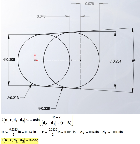
Figure 7: Gage Ball Example with Large Ball Protruding from the Hole.
For more information on using gage balls, see this reference.
Appendix A: Another Worked Example
Figure 8 shows an example that I worked in Visio.

Figure 8: Another Worked Example.
Pingback: Measuring Countersink Diameter Using Gage Balls | Math Encounters Blog