
Introduction
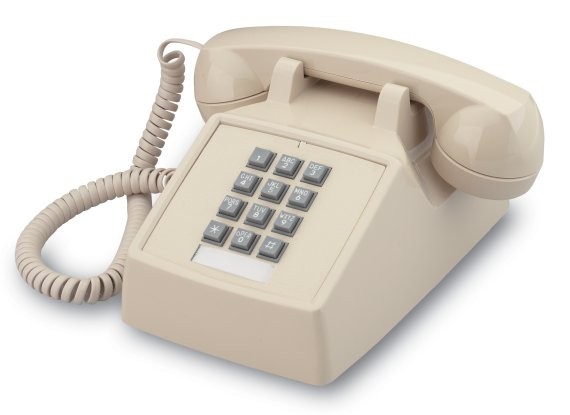
Figure 1: Old Bell 2500 Series Phone.
I just saw a customer report of phone ringing issues with an old 2500 series phone (Figure 1). While these are good phones, they can be difficult for Fiber-to-the-Home (FTTH) deployments because they have 1 Ringer Equivalence Number (REN) ringers. By specification, homes are permitted to have as many as five of these phones (5 REN total load) on a single line and they will still ring with proper volume. To support this requirement, modern Subscriber Line Interface Circuits (SLICs) used to ring phones in FTTH products are designed to drive a 5 REN load. However, some of these old phones appear to have not aged well and they are becoming difficult to ring – they behave as if their equivalent load on the line is now more than 1 REN. In fact, I just saw one with a 1.1 REN rating when it was new.
The specifications for ringing a phone require that the ring voltage be 40 VRMS with a 5 REN load. I had a conversation with an old POTS engineer today about how to compute the RMS ring voltage on at a phone and I thought I would document this discussion here. This is a routine question, but we have a new engineer who wants to see how the calculation is performed. I decided the best way help would be to provide a worked example.
Background
Definitions
A few definitions are useful to review.
- Ringer Equivalence Number (REN)
- The electrical load placed on a phone line by the single electric bell of a Model 2500 phone, which we call a REN. In the US, the number of these old phones allowed on a line is limited to 5, which is called a “5 REN load”. In impedance terms, one REN is equivalent to a 6930 Ω resistor in series with an 8 µF capacitor – a 5 REN load has 5 of these series components in parallel.
- Feed Resistance
- All phone circuits need to have protection circuit on their inputs. These circuits protect against nasty realities like AM radio interference (I have frequently heard radio stations on phone lines), lightning, and foreign voltages (e.g. high voltage inadvertently put on phone lines because of an errant nail or screw). These protection circuits have a resistance associated with them that I model with the feed resistance.
- Line Resistance
- The resistance of the phone line. The resistance of the phone line is related to its length (500 feet or 1000 feet), wire gauge, and temperature.
- Symmetrical Ringing
- A ring voltage waveform that is symmetrical about 0 V. Some older systems used a sine wave with a DC level added to it, which was referred to as asymmetrical ringing. I do not see this type of ringing very often today.
- SLIC Voltage Drop
- The voltage drop in the POTS supply voltage as it passes through the SLIC on the way to the tip and ring lines. In general, it is a function of the current being placed on the tip and ring lines.
Circuit Model
A ringing phone circuit modeled using the equivalent circuit shown in Figure 2. I will assume that the phone is the only circuit element with a reactive component.

Figure 2: Phone Ringing Circuit Model.
Analysis
Approach
I am using this analysis as a reference example for a new engineer to use for a design he is working on. I am not using any particular hardware, but instead I am using typical values that I have seen over the years. I will be assuming a symmetrical ring voltage with a sinusoidal shape. Personally, I like to use trapezoids for ring voltage waveforms on short phone lines, but this particular application will use sinusoidal waveforms.
Power System Model
Figure 3 shows how I modeled both the power supply output voltage (VSupply) and the voltage drop (VSLIC_Drop) through the SLIC.

Figure 3: My Model of the Power System Voltages Versus Current.
Ring Voltage Model
Figure 4 shows my calculation for the ring voltage RMS value. I do mention some measured ring voltage values in the calculation that I have from a circuit we designed years ago for comparison with my calculations.

Figure 4: Calculations of Ring Voltage For Two Configurations.
Conclusion
My rough model put together from memory gave me results similar to those of a deployed system, so I feel that the model is pretty close to accurate. The analysis should provide our new telephony engineer a model for how to proceed with his application.