
Quote of the Day
Einstein himself, of course, arrived at the same Lagrangian but without the help of a developed field theory, and I must admit that I have no idea how he guessed the final result. We have had troubles enough arriving at the theory - but I feel as though he had done it while swimming underwater, blindfolded, and with his hands tied behind his back!
— Feynman Lectures on Gravitation (1995) p.87. Feynman was showing how to derive the theory of general relativity. Even Feynman struggled to understand how Einstein obtained his theory of general relativity given the state of knowledge at the time.
Introduction

Figure 1: Example of Measuring a Small Angle.
While I covered angle measurement in a previous post, that approach can be difficult to apply for acute angles. The approach presented in this post works well for acute angles, but will not work for obtuse angles.
As part of this post, I will also demonstrate how to perform a tolerance analysis on this approach. The tolerance analysis is important in understanding the level of accuracy required in your linear measurements to achieve the desired angle accuracy.
This example was motivated by material presented on this web page.
Background
All the background required is covered in my previous metrology posts:
- Measuring Round-Over Radius Using a Roller Gage
- Angle Measurement Using Roller Gages
- Radius Measurement Using Roller Gages
Analysis
Definition and Derivation
Figure 2 show the configuration of the two roller gages of diameter D with the angle. A slip gage is used to measure the distance L between the outer gage and the upper leg of the angle. I have included a red-legged reference triangle in Figure 2. The formula for θ is found by applying the definition of the sin of angle (opposite/hypotenuse). This means that 

Figure 2: Symbol Definitions.
Example
Figure 3 show the calculations associated with the example of Figure 1. My results are in reasonable agreement with the angle measurement taken from the Figure 1, which is a scale drawing.

Figure 3: Calculations For Example of Figure 1.
Tolerance Analysis
Figure 4 shows how I performed my tolerance analysis. In this analysis, I wanted to estimate the impact of tolerance errors in the roller (±0.0001 in) and slip gages (±0.001 in). These errors produce an error in the angle measurement of 2.5 arcminutes.
The error analysis makes use of the concept of differentials.
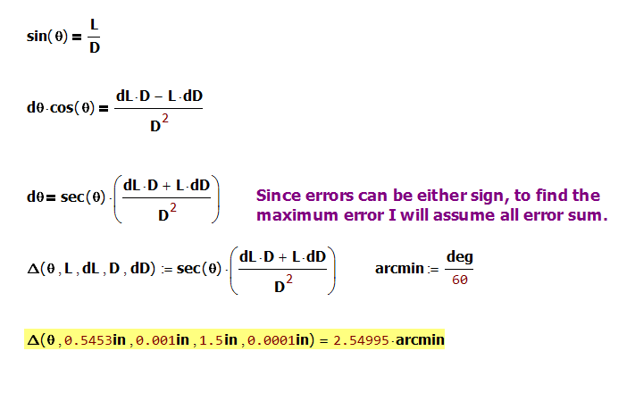
Figure 4: Error Analysis.
Conclusion
This post ends my series on using roller gages and gage balls. This effort has been part of my attempts to gather information and tutorials on making accurate measurement of tough parameters.
The most accurately machined spheres ever manufactured (about the size of a ping-pong ball) are now orbiting the Earth in gyroscopes that are part of a project to prove that Einstein was right:
https://einstein.stanford.edu/TECH/technology1.html