
Quote of the Day
The secret to living well and longer is: eat half, walk double, laugh triple, and love without measure.
— Tibetan Proverb
Introduction

Figure 1: Side Angle Measurement of Slot. (Source)
I thought I was done with my metrology review when I encountered an excellent set of discussions at the Hobby-Machinist web site. They advertise themselves as "The Friendly Machinist Forum," and all signs indicate that is true. In addition to excellent tutorials, there are some first-rate metrology discussions on that site, and I want to document a few of the examples that are shown there.
Figure 1 shows a slot with angled sides with the angle being measuring using gage balls or roller gages.
Analysis
Derivation

Figure 2: Reference Drawing Showing Critical Variables for Measuring One Angle.
The math behind this example is almost identical to that presented in this post, where I present Equation 1 as the angle solution for the measurement scenario of Figure 2.
The differences are created by my distance measurements, L1 and L2, are doubled in Figure 1 because I am measuring two angles at once. This means that I can easily adapted Equation 1 to the configuration of Figure 1 with a simple substitution.
| Eq. 1 | 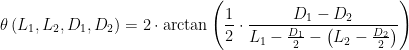 |
where
- L1 is the distance from reference to outside edge of roller gage.
- L2 is the distance from reference to outside edge of roller gage.
- D1 diameter of the first roller gage.
- D2 diameter of the second roller gage.
- θ is the angle of the drill hole relative to the surface that is drilled.
I can redefine my symbols as shown in Figure 3 and generate a new formula, Equation 2, that applies to Figure 1.

Figure 3: Variable Definitions for Figure 1.
To obtain Equation 1 from Equation 2, you apply the substitutions 

| Eq. 2 |  |
where
- L'1 is the distance between the small diameter gages.
- L'2 is the distance between the large diameter gages.
- D1 diameter of the first roller gage.
- D2 diameter of the second roller gage.
- θ is the side angle relative to the slot base.
Figure 1 Example
Figure 4 shows how to work the example of Figure 1. My formula results agree with those obtained from the scale drawing.

Figure 4: Example of Figure 1 Worked Using Equation 2.
Conclusion
My plan is to continue to build up my metrology examples so that I have as complete a set as I can put together.
I've been following all these metrology examples with interest. I used to be a machinist and my favourite machine tool was a universal miller. Measuring without disturbing the setup was always the big challenge and a good set of slip gauges and a good micrometer were the essential requirements. I use to use a Starrett micrometer, manufactured in the US probably before I was born but still going strong in the 1970s. The machine tools in one company where I worked in those days were sadly not up to scratch, having been built to wartime standards but they were gradually being replaced with new machines and my old clapped out milling machine was replaced with a brand new "Huron" universal miller. It was an absolutely brilliant machine with unique design features, the main one being the mitre on the head which meant it converted from vertical to horizontal operation in minutes. I always used to think these were US manufactured, probably because of the North American Indian logo, but in fact they are French made and unlike most UK machine tool companies, they are still going strong.
I developed my interest in metrology while working on precision measurement electronics for the automotive industry, mainly by Chrysler and transmission manufacturers. I found the subject so interesting! On the personal side, I have some home projects that require machinist skills, which I am working on acquiring now.
I use this blog as a searchable database of my personal notes – these notes go back in paper form nearly 35 years. I am always pleased when others find them useful. Thanks for reading my blog and sending me a note.
mark