
Quote of the Day
Unfortunately, although the electrical and thermal differential equations are analogous, it is erroneous to conclude that there is any practical analogy between electrical and thermal resistance. This is because a material that is considered an insulator in electrical terms is about 20 orders of magnitude less conductive than a material that is considered a conductor, while, in thermal terms, the difference between an 'insulator' and a 'conductor' is only about three orders of magnitude. The entire range of thermal conductivity is then equivalent to the difference in electrical conductivity of high-doped and low-doped silicon.
— Clemens J. M. Lasance, Thermal Engineer for Philips. As an electrical engineer, I use lumped parameter models with confidence because I know that my insulators really insulate. The thermal engineer does not have that luxury.
Introduction

Figure 1: ADN4612 Pin Diagram. (Source)
An engineer stopped by my cube today and asked a question about how to estimate the junction temperature of a part on a circuit card that may have an over-temperature problem. Using the common thermal resistances (θJA and θJC), he was obtaining nonsensical results. This problem was a good illustration of the difficulties present in estimating Integrated Circuit (IC) junction temperatures using the commonly supplied thermal resistances.
I will show how I went about estimating the junction temperature of this device and why the methods usually used can provide unrealistic results. My results are estimates, but show that the junction temperature of the ADN4612 is significantly lower than its maximum rating and does not warrant any further analysis. If it were close, I would bring in a mechanical engineer to perform a more detailed thermal analysis.
Background
Problem Statement
With respect to ADN4612's junction temperature in this application, the following characteristics are relevant :
-
-
- power dissipation: PD = 3.5W
- top of case temperature: TTop = 105°C (measured with thermocouple)
- via temperature under part: TPCB = 82°C (measured with thermocouple by a via under the part)
- package: 88-pin Lead Frame Chip Scale Package (LFCSP )
- junction-to-ambient thermal resistance: θJA = 24°C/W
- junction-to-case thermal resistance: θJC = 1.7°C/W
- maximum allowed junction temperature: TMax = 125°C/W
-
Issues Using Common Thermal Resistances
IC specifications commonly give two thermal resistances, θJA and θJC. These specifications are useful, but frequently misused. The key to their proper use is to understand how they are measured. θJA is measured on a standard PCB as defined by JEDEC JESD51-2. Since every circuit board design is different, θJA is only useful for comparing the relative thermal performance of different packages. It is not useful for predicting component temperatures on a specific PCB and environment that are different from the test configuration.
θJC is measured in a special jig that forces all the heat through some area on the IC's case. For most ICs, the heat is forced through the top of the case. This makes sense if you are going to put a heat sink on the part and your plan is for most of the heat to go out the top. In the case of the ADN4612, it has a copper slug on the bottom of the part. θJC for the ADN4612 is measured by forcing all the heat through the bottom of the part and into the PCB. Again, this situation is not what actually occurs – the part will dissipate heat into the environment through multiple paths (bottom, top, leads).
Ideally, we would thermal models that provided use thermal resistances for all the possible paths for heat to leave a part. These models, called compact thermal models, do exist, but most vendors do not supply all the required parameters (e.g., Figure 2).

Figure 2: Example of a Compact Thermal Model for an IC (also known as Delphi model). (Source)
While compact thermal models for every part would be great, most ICs are not going to have temperature issues. An electrical engineer wants a rough estimate of the junction temperature to determine if he needs to bring in a mechanical engineer for a more detailed analysis of a specific part. For this approximate type of work, I prefer to use Psi-JT (ΨJT). This parameter is NOT a thermal resistance and is referred to as a thermal characteristic. It also is defined in JESD51-2. The standard allows for making a simple linear estimate of a part's junction temperature in a typical application using Equation 1.
| Eq. 1 | 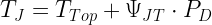 |
where
- TJ is the IC junction temperature.
- TTop is the measured case temperature on the top of the part (the easiest place to get a measurement).
- PD is the part power dissipation.
- ΨJT is the thermal characteristic between the junction and the top of the IC case.
Unfortunately, Analog Devices did not provide ΨJT on their datasheet. This is where a bit of digging comes in …
Analysis
Obtaining ΨJT
Because the datasheet did not contain ΨJT, I started using my usual search engine to do some specification hunting. It turns out that I did find a couple of references to ΨJT for similar packages:
- an Analog Devices forum discussion on the 24-pin version of this package, which gave a 0.9°C/W for ΨJT.
- an Analog Devices forum discussion on the 20-pin version of this package, which gives a simulated value of 0.27°C/W for ΨJT. The difference between a simulated value and measured value like this does not shock me at all.
We can also calculate an approximate ΨJT value using the method I outline on this blog post (Figure 3).

Figure: 3: ΨJT Estimate Using Approximation.
For my calculations below, I will assume the worst-case ΨJT value I found of 0.9 °C/W.
As a cross-check, I can also make an approximation using ΨJV: junction-to-PCB via thermal characteristic, which I obtained from this chart (Figure 4).

Calculations
Figure 5 shows my calculations to estimate the junction temperature for the ADN4612 using two different parameters: ΨJT and ΨJV.

Figure 5: Two Ways to Estimate Junction Temperature.
Conclusion
I view my two estimates of junction temperature (108°C and 103°C) as reasonable close for this type of approximate calculation. Both methods show that the part is not operating near its junction temperature limit of 125°C, which is what I needed to know.
I do wish the semiconductor vendors would provide designers with better thermal data and models that would make applying their parts easier. I should not have to search the web and crawl around forum discussions in order to intelligently use a vendor's part.