
Quote of the Day
It is a universal truth that the loss of liberty at home is to be charged to the provisions against danger, real or pretended, from abroad.
— James Madison
Introduction

Figure 1: Angle Measurement Example.
I am continuing to work through some basic metrology examples – today's example uses roller gages to measure the angle of a drilled hole (Figure 1). The technique discussed here uses two roller gages and a plug. The plug must fit the hole snugly (i.e. no backlash) as it will provide the surface that we will be measuring. Using this approach assumes that you need a very accurate measurement of a hole's angle as rough measurements can be made using a protractor.
Background
This example is based on the material found on this web page. I will derive the angle relationship presented there (Equation 1) and present a worked example that is confirmed using a scale drawing (Figure 1).
| Eq. 1 | 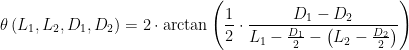 |
where
- L1 is the distance from reference to outside edge of roller gage.
- L2 distance from reference to outside edge of roller gage.
- D1 diameter of the first roller gage.
- D2 diameter of the second roller gage.
- θ is the angle of the drill hole relative to the surface that is drilled.
These variables are all indicated in Figure 2.

Figure 2: Reference Drawing Showing Critical Variables.
Analysis
Derivation
Figure 3 shows how to derive Equation 1. The basic derivation process is simple:
- The center of each roller gage is on a line that is makes an angle of θ/2 with the plug.
- The slope of line connecting the roller gage centers has the value tan(θ/2).
- The line's slope is computed using the rise (
) and run (L1–L2) values shown in Figure 2.

Figure 3: Derivation of Angle Relationship.
Example
Figure 4 shows works through the angle calculation example of Figure 1.

Figure 4: Worked Example Using Values From Figure 1.
Conclusion
I have some designs I plan to build that have angled holes. This procedure will give me a way to accurately measure the angle of these holes.
Pingback: Another Angle Measurement Using Roller Gages Plus Error Analysis Example | Math Encounters Blog
Pingback: Tapered Side Angle Measurement | Math Encounters Blog